Solución
Conversion of torque according to the formula \(M_s=9550\cdot \frac{N [kW]}{n [rpm]} M_s=9550\cdot \frac{10}{955}=100 Nm\)
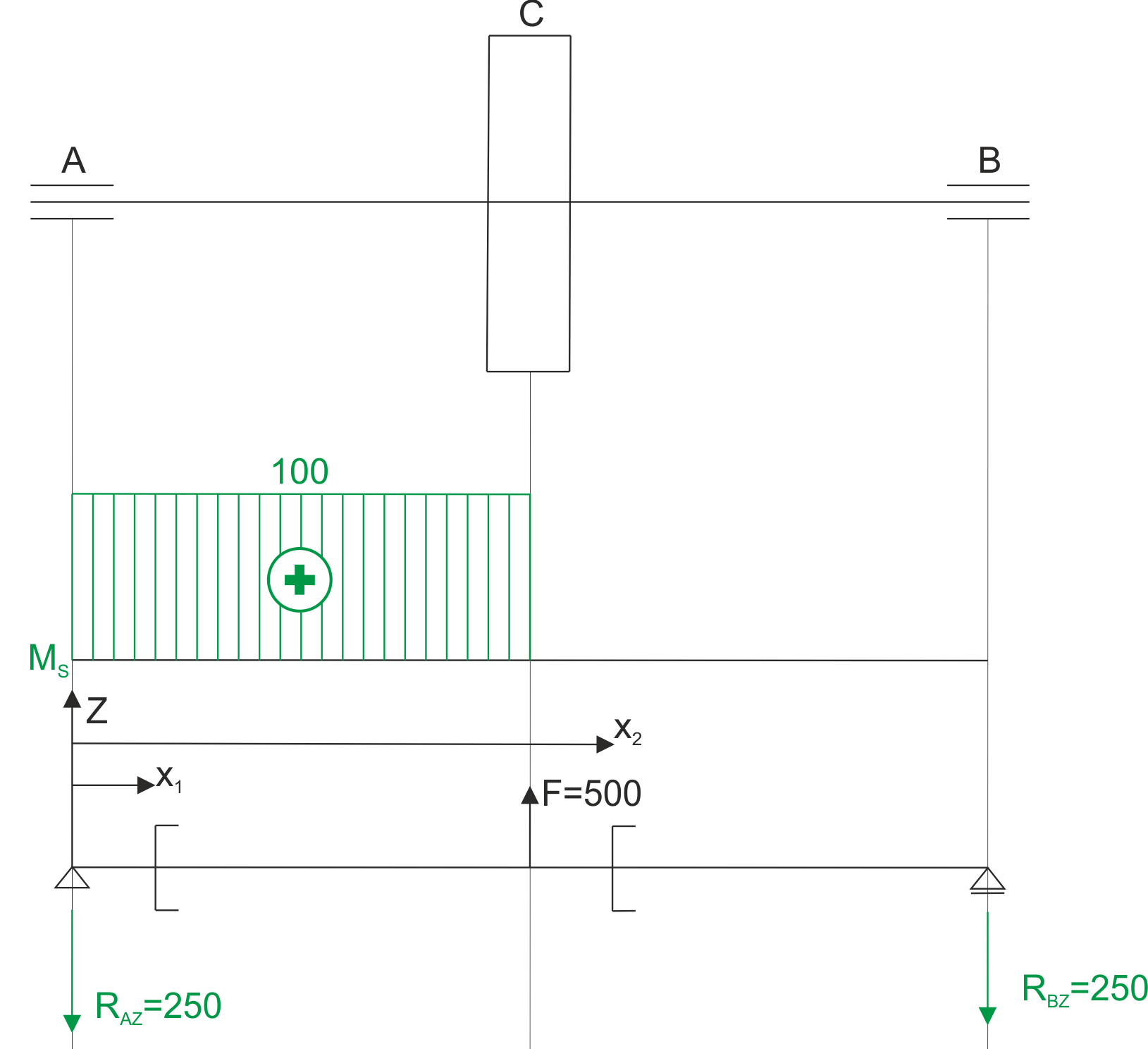
The force F on the arm of half a pulley receives the torque that is applied by the engine at the beginning of the shaft. Torque occurs between the engine and the pulley. We calculate the force F on the pulley.
\begin{aligned} &F\cdot 0.2=100\Rightarrow F=500 N\\ \end{aligned}We are dealing with bending of the shaft in one plane and torsion.
Torque diagram and bending torque calculation diagram.
 \begin{aligned}
&x_{1} \in(0 ; 0.5) \\
&M\left(x_{1}\right)=-R_{A Z} \cdot x_{1} \\
&M(0)=0 N m \\
&M(0.5)=-125 N m \\
&x_{2} \in(0.5 ; 1) \\
&M\left(x_{1}\right)=-R_{A Z} \cdot x_{2}+500 \cdot\left(x_{2}-0.5\right) \\
&M(0.5)=-125 N m \\
&M(1)=0 N m
\end{aligned}
Bending moment diagram.

We calculate the value of the equivalent moment at characteristic points.
\begin{aligned} &M_{z a s}=\sqrt{M_{g}^{2}+\frac{3}{4} M_{s}^{2}} \\ &M_{z a s}^{A}=\sqrt{0^{2}+\frac{3}{4} \cdot 100^{2}}=86.6 \mathrm{Nm} \\ &M_{z a s}^{C A}=\sqrt{125^{2}+\frac{3}{4} \cdot 100^{2}}=152.1 \mathrm{Nm} \\ &M_{z a s}^{C B}=\sqrt{125^{2}+\frac{3}{4} \cdot 0^{2}}=125 \mathrm{Nm} \\ &M_{z a s}^{B}=\sqrt{0^{2}+\frac{3}{4} \cdot 0^{2}}=0 \mathrm{Nm} \end{aligned}Equivalent moment diagram

We dimension the shaft for the maximum equivalent moment. We use the derived formula
\begin{aligned} &M_{z a s}^{\max }=152.1 \mathrm{Nm} \\ &d \geq \sqrt[3]{\frac{32 M_{z a s}}{\pi \cdot k_{g}}} \\ &d \geq 0.0295 \mathrm{~m} \\ &d=3 \mathrm{~cm} \end{aligned}