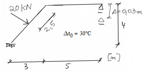
Solution
Determining the degree of kinematic indeterminacy
\begin{aligned} &SKN=\sum \varphi +\sum \Delta\\ &SKN=1+0=1\\Adoption of the basic system of displacement method
UPMP
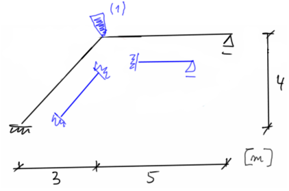
Determining the unit state
state \( \varphi_1 =\overline{1} \)
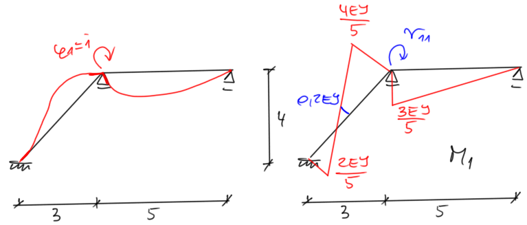
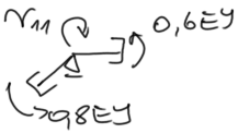
| Spacing Spacing | \begin{aligned} & \Sigma M=0 \\ & r_{11}=1,4 E I \end{aligned} |
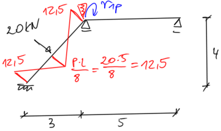
state P
| Spacing Spacing |
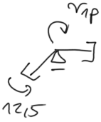
\begin{aligned} & \Sigma M=0 \\ & r_{1p}=12,5 \end{aligned} |
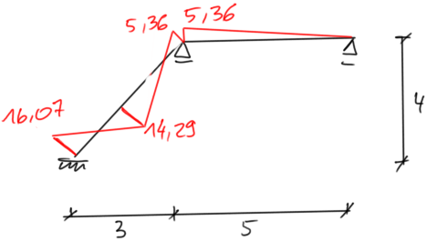
| \begin{aligned} & M_{o s t}^P=M_1 \cdot \varphi_1+M_p \\ \\ & M_A=0,4 E J \cdot \varphi_1-12,5=-16,07 \mathrm{kNm} \\ & M_B=-0,2 E J \cdot \varphi_1+12,5=14,29 \mathrm{kNm} \\ & M_{C d}=-0,8 E J \cdot \varphi_1-12,5=-5,36 \mathrm{kNm} \\ & M_{C P}=0,6 E J \cdot \varphi_1=-5,36 \mathrm{kNm} \end{aligned} | Spacing Spacing |
|
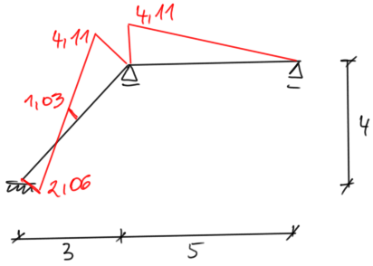
state G
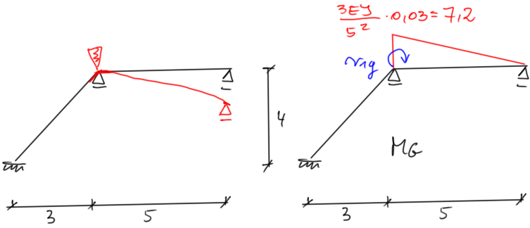
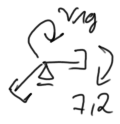
| Spacing Spacing | \begin{aligned} & \Sigma M=0 \\ & r_{1g}=-7,2 \end{aligned} |
| \begin{aligned} & M_{o s t}^G=M_1 \cdot \varphi_1+M_G \\ \\ & M_A=0,4 E J \cdot \varphi_1=2,06 \mathrm{kNm} \\ & M_B=-0,2 E J \cdot \varphi_1=-1,03 \mathrm{kNm} \\ & M_{C d}=-0,8 E J \cdot \varphi_1=-4,11 \mathrm{kNm} \\ & M_{C p}=0,6 E J \cdot \varphi_1-7,2=-4,11 \mathrm{kNm} \end{aligned} | Spacing Spacing |
|
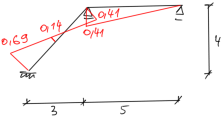
state \( \Delta T0 \)
The elongation of the horizontal bar (let's assume = "a") does not cause any charts, the sliding support moves to the right.Let's calculate the elongation of the inclined rod:
\( \Delta l=\alpha \cdot \Delta \text { to } \cdot l=10^{-5} \cdot 30 \cdot 5=1,5 \cdot 10^{-3} \mathrm{~m} \)
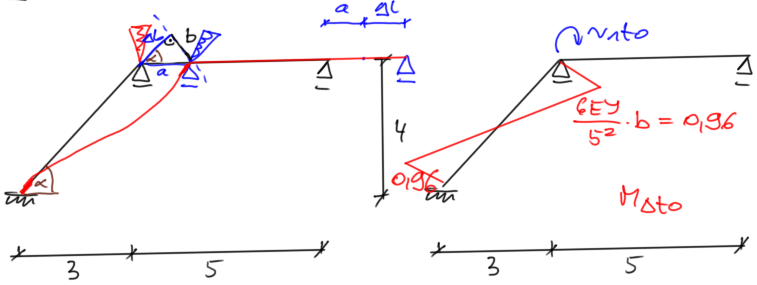
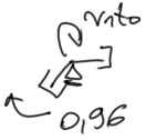
| Spacing Spacing | \begin{aligned} & \Sigma M=0 \\ & r_{1t0}=-0,96 \end{aligned} |
| \begin{aligned} & M_{o s t}^T=M_1 \cdot \varphi_1+M_{\Delta T0} \\ \\ & M_A=0,4 E J \cdot \varphi_1-0,96=-0,69 \mathrm{kNm} \\ & M_B=-0,2 E J \cdot \varphi_1=-0,14 \mathrm{kNm} \\ & M_{C d}=-0,8 E J \cdot \varphi_1+0,96=0,41 \mathrm{kNm} \\ & M_{C p}=0,6 E J \cdot \varphi_1=0,41 \mathrm{kNm} \end{aligned} | Spacing Spacing |
|
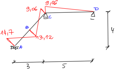
Connection of final bending moment charts
\begin{aligned} & M_{\mathrm{A}}=-16.07+2.06-0.69=-14.7 \mathrm{kNm} \\ & M_{\mathrm{B}}=14.29-1.03-0.14=13.12 \mathrm{kNm} \\ & M_{\mathrm{Cd}}=-5.36-4.11+0.41=-9.06 \mathrm{kNm} \\ & M_{\mathrm{Cp}}=-5.36-4.11+0.41=-9.06 \mathrm{kNm} \end{aligned}
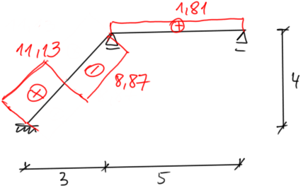
Determining the final shear force chart by balancing the frame elements
Element AC: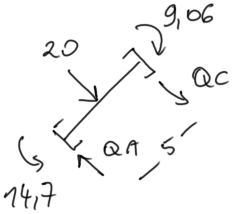
\begin{aligned} & \sum M_A=0 \\ & -14,7+20 \cdot 2,5+9,06+ \\ & +Q_C \cdot 5=0 \\ & Q_C=-8,87 \mathrm{kN} \\ & \sum M_C=0 \\ & -14,7-20 \cdot 2,5+9,06+ \\ & +Q_A \cdot 5=0 \\ & Q_A=11,13 \mathrm{kN} \end{aligned} |
Element CD:
\begin{aligned} & \Sigma M_C=0 \\ & -9,06+Q_D \cdot 5=0 \\ & Q_D=1,81 \mathrm{kN} \\ & \Sigma y=0 \\ & Q_C=Q_D \end{aligned} |
Final shear force chart [kN]
Determining the final normal force chart by balancing the node
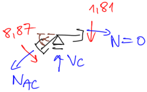
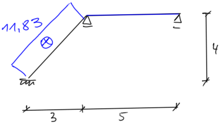
| Spacing Spacing | \begin{aligned} & \sin \alpha=0,8 \quad \cos \alpha=0,6 \\ & \Sigma x=0 \\ & -N_{A C} \cdot \cos \alpha+8,87 \cdot \sin \alpha=0 \\ & N_{A C}=11,83 \mathrm{kN} \end{aligned} |
Final normal force chart [kN]
If you have any questions, comments, or think you have found a mistake in this solution, please send us a message at kontakt@edupanda.pl.
